 |
The waterjets function as in the full-size vehicle. In the photo at left, the diverter is open for forward thrust. If the diverter is closed, water is thrown forward through the vanes (easier to see in the next photo). |
 |
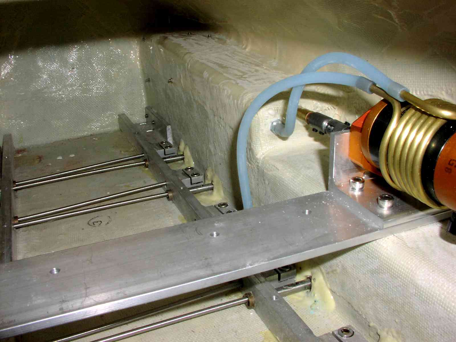
This side view shows the drive shaft, the cooling water pickup line, and the jet body. What it doesnt show is a fender plate that I havent made yet. The fender will be made of 1/16" stainless sheet. Its purpose is primarily to keep the jet from sucking in air. With the plate installed, the only way for water to get to the suction side of the jet is between the top of the tracks and the bottom edge of the fender. |
 |
A view from the front. The propeller is an Octura 3 blade berrylium job. 57mm diameter. |
 |
This is the back side of the jet body, with the cooling water pickup which has been silver-soldered in. When I am certain that there will be no more welding or soldering I intend to fill the void between the tapered reducer (the inside shiny circle) and the jet body with rubber, to reduce hydraulic losses. |
 |
The next few photos show the motor mounts, u-joints and cooling jackets for the motors. Try to avoid noticing the receiver battery pack that, for some reason, is laying on top of the motor. |
 |
|
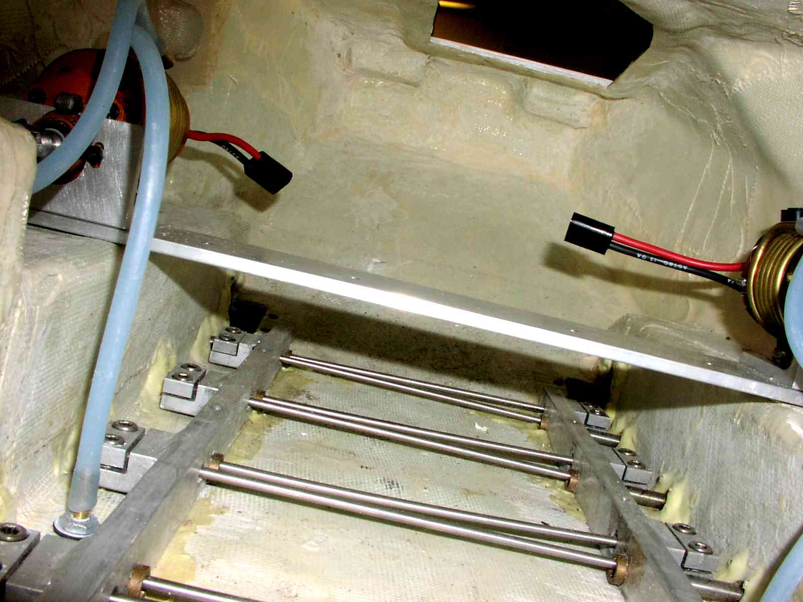 |
This is a view looking forward. The track drive motors, which obviously are not installed in this photo, mount to the same transverse plate that the water jet motors mount to. |
 |
|
 |
I recently installed and tested the water jets, with the hull loaded to scale weight of 65 lbs. Scale speeds take only about 4 amps per motor (96 watts at 24 volts). At 10 amps or so per motor, the model moves much faster than scale, so it should have no problems getting ashore. At full throttle, each motor promptly blows its 20 amp fuse.