The full-size AAVP7A1 uses a torsion bar and road arm for each road wheel. The model uses the same sort of suspension. The suspension parts for the model are shown below.
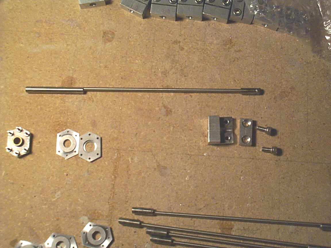 |
At left is a torsion bar, and below it an assembled hull
bearing plate, unassembled hull bearing plate components, and an unassembled torsion bar
anchor/adjuster. The torsion bar is 0.133" stainless spring wire that has been spot welded to 0.25" stainless shaft at each end. Before welding, a slot was milled into the 0.25" shaft pieces to fit the spring wire. Following welding, I used a lathe to remove any weld metal that would keep the assembly from fitting into a 0.25" bronze bearing. The bearing plate halves are aluminum. The rear plate is bored to accept a press fit bronze oilite bearing. The front plate has a recess bored on the backside to accomodate a teflon seal. One bearing plate assembly is shown bolted together (for final assembly, those bolts will penetrate the hull and hold the bearing plate to the vehicle). |
 |
The hull has been routed to fit the bearing plate halves. This was necessary because the bearing plate halves and teflon seal were thicker than scale. |
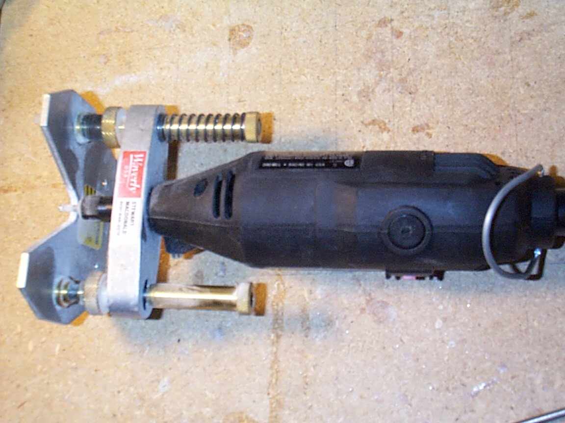 |
To route the hull, I used a router base for my Dremel. I didnt even know these were available until I realized I had a bearing plate clearance problem. This unit comes from Stewart MacDonald's, a guitar builders supply house and costs only $45. |
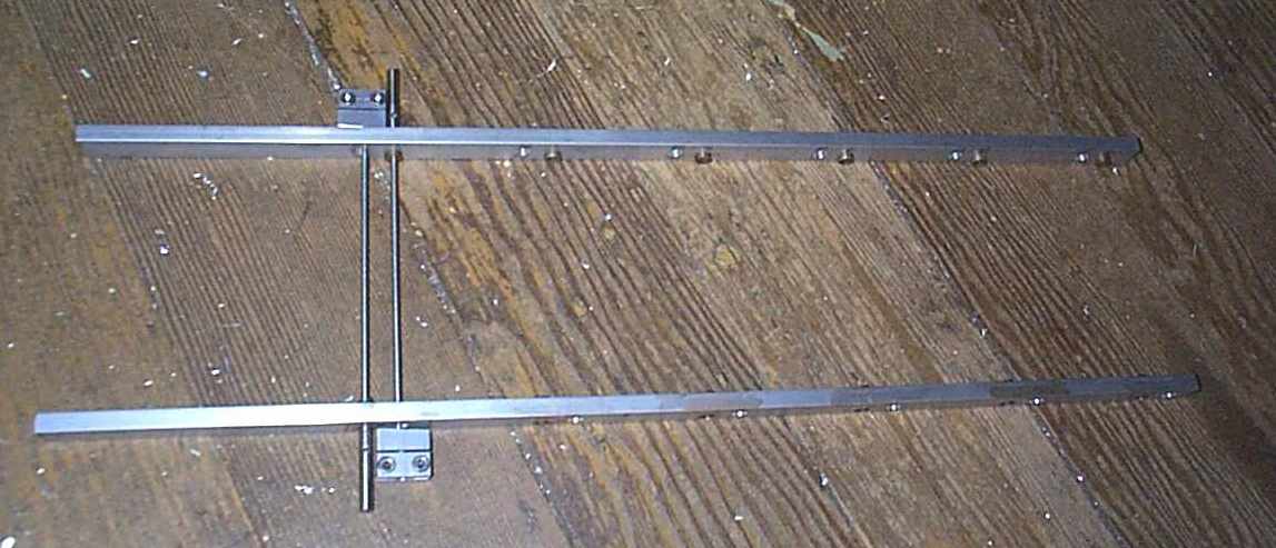 |
On the inside of the hull, 3/8" x 3/4" rails support interior road arm bearings and the torsion bar anchors. The interior bearings are unflanged oilite bearings that are pressed into bored holes in the rails. |
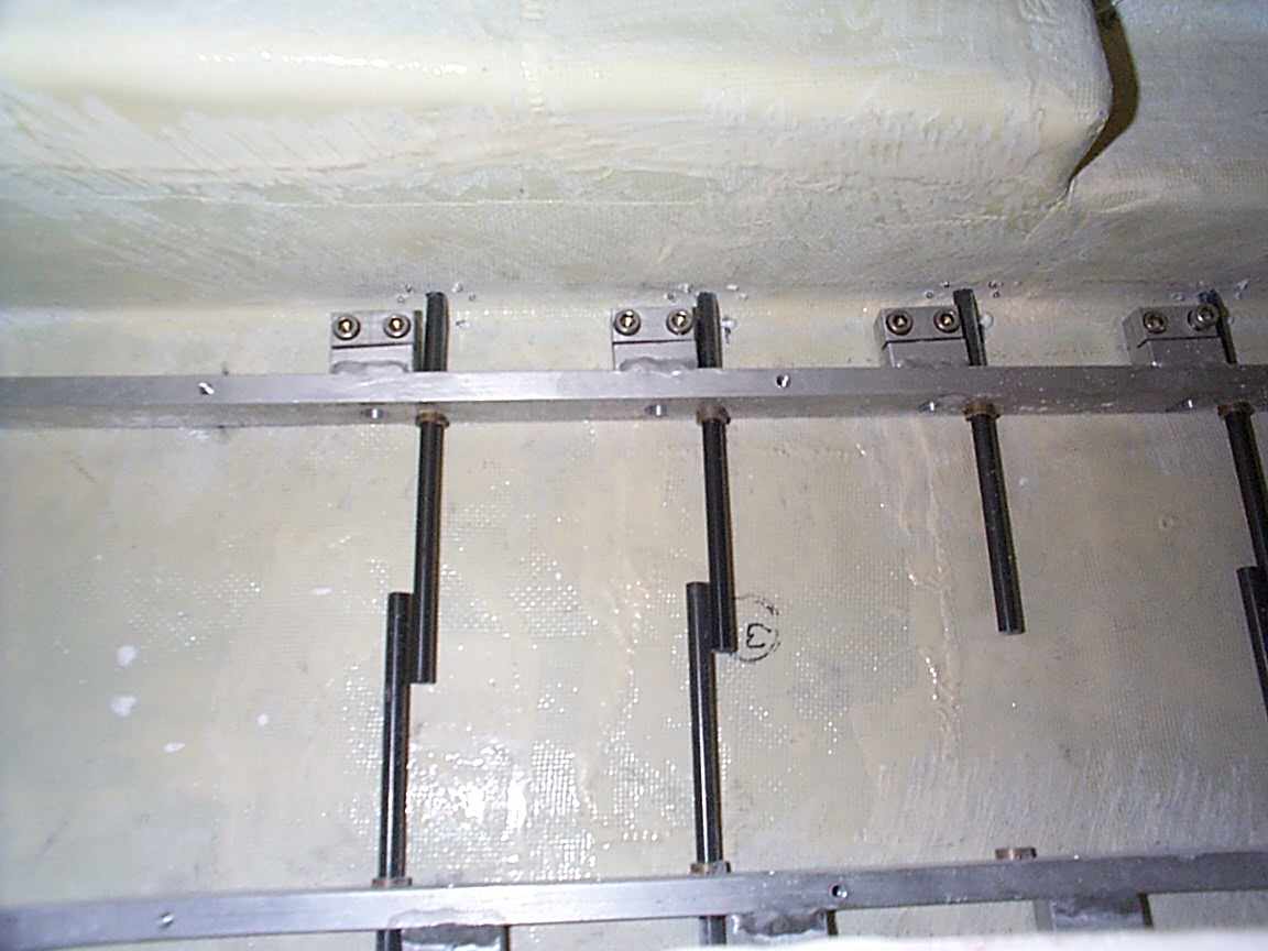 |
The torsion bar anchors have been welded to the rails, and
the rails bolted to the floor of the AAV. The black 1/4" shafts are installed
for alignment testing. Note: wear long sleeves when welding to avoid arc-burn |
 |
Another shot of the test fit, this time with the camera inside the hull. Everything is a little dusty due to final grinding of the fiberglass hull to clear the bronze bearings. Grinding fiberglass always has a very itchy aftermath. |
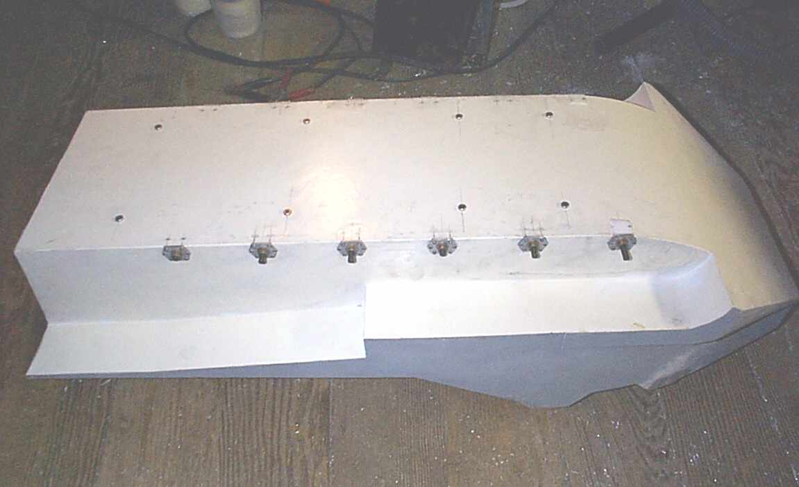 |
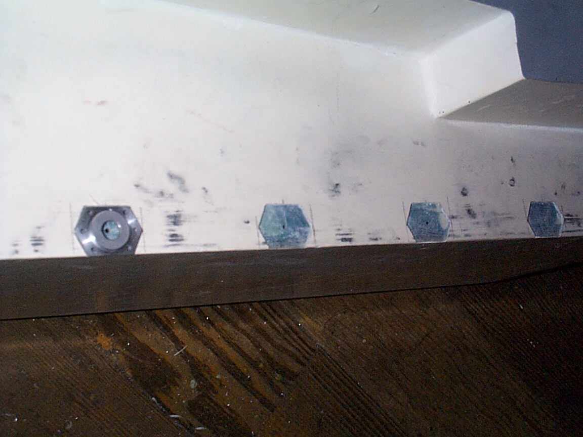
A view of the test fit-up from the hull bottom. The suspension rails are held to the hull by some not so scale looking torx screws. |
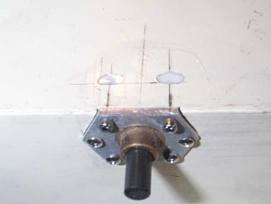 |
A close up of a bearing plate. The bearing plates are
held in place by 6 each 2-56 screws. The upper 4 bolts are easy to install.
The bottom 2 bolts require that nuts be installed in the plane of the hull floor.
In this photo you can see the holes that were routed so that those nuts can be installed -
the holes have since been backfilled with an epoxy/glass bead mix. Note that only the innermost piece of the bearing plate is installed for this test fit, and that the broze bearing is installed inside-out to facilitate the test-fit. |
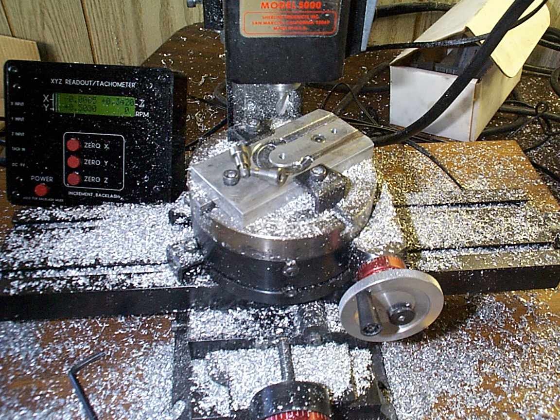 |
October 10, 1999, the saga continues: Because I am working in aluminum, I made the road arms a little thicker than scale. Scale thickness arms would be likely to bend when driving in rough terrain. To make the road arms, I started with 3/8" aluminum plate and drilled and reamed 1/4" holes for the torsion bar and axle. The road arms are rounded at each end. To make it easier to hold onto the pieces while cutting these curves, I made a custom jig. The jig bolts to the Sherline rotary table and has tapped holes for shoulder bolts that are inserted through the road arm's 1/4" drill holes. The photo at the left shows the jig. |
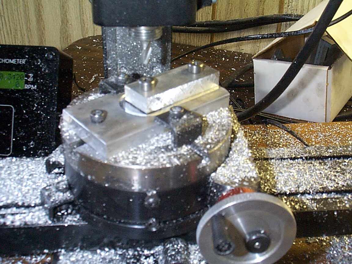 |
A block of 3/8" aluminum bolted into the road arm cutting jig. After cutting the radius at the torsion bar end of the arm, the arm is reversed. I then cut the sides by locking the table at zero degrees, setting the appropriate 'Y' axis offset and useing 'X' axis travel. Finally I cut the radius at the wheel end of the arm. |
 |
The final step is to drill a 5/64" hole through each road arm and torsion bar and assemble them with stainless spring pins. At left is the collection of torsion bars assembled to road arms. |
It is hard to gauge whether the torsion bars will be too stiff, because it is not clear what the spring constant of my spring wire and the extent to which spot welding may have altered that constant at the wire ends. I'll know once the project is ready for a test drive. If anything, the .133" wire will prove to be too stiff. Fortunately, the spring wire is available in many diameters so the torsion bars can be swapped out for lighter duty bars at any time.